Wednesday, May 31, 2017

How Does EDFA Amplifier Work for Extending DWDM System?

EDFA amplifier is the most common optical amplifier, used for boosting optical signals in optical applications, especially the DWDM systems. It is the key amplification device deployed in the optical system to enhance the signal power, so that the optical transmission distance can be greatly extended. Undoubtedly, the EDFA amplifier is an ideal choice for long-haul DWDM system. But how does it work for extending DWDM system? As shown in the following figure, EDFA amplifier can be placed at the transmitting side of the DWDM link, any intermediate point along the transmission DWDM link and the receiving end of the DWDM link, separately working as booster amplifier (or post-amplifier), in-line amplifier (or optical line amplifier) and pre-amplifier for optimizing the DWDM system reach. Let’s study the related knowledge in details.
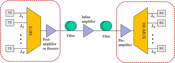
EDFA amplifier in DWDM network

What’s EDFA Amplifier?
EDFA amplifier is a kind of optical amplifier that can directly amplify any input optical signal without the need of optical-electrical-optical conversion. It can not only save the cost for long-haul transmission, but also reduce the signal loss and unwanted noise, compared to the traditional optical-electrical-optical amplification. As the fiber attenuation limits the reach of a non-amplified fiber link to about 200 km, EDFA amplifier is an ideal choice for building wide area purely optical networks.

How Does EDFA Amplifier Work?
As mentioned before, EDFA amplifier can be deployed in three places of the DWDM link to make the power compensation, the transmitting side of the link, the intermediate point along the link and the receiving end of the link. If placed at the transmitting side, it can be called as booster optical amplifier or post-amplifier, offering high input power for the wide fiber span. If placed at the intermediate point along the link, you can call it in-line amplifier or optical line amplifier. The optical line amplifier is used for compensating the fiber loss in the transmission link. When you call it pre-amplifier, it must be deployed in the receiving end, for boosting the signal power to the the necessary receiver level. The following will introduce these three different deployments of EDFA amplifier and how does the it work in the three link.
Placed at the Transmitting Side: in this application, we always call EDFA as booster optical amplifier that features high input power, high output power and medium optical gain. It can directly amplify the aggregated optical input signal multiplexed by the DWDM Mux Demux, to achieve DWDM network transmission distance extension. By placing the EDFA amplifier at the transmitting side of the DWDM link, the transmitted signal power can be enhanced to the necessary transmitting level and the optical loss caused by the laser and optical fibers can be also compensated. Hence, the EDFA booster optical amplifier is always deployed when the DWDM Mux Demux attenuates the signal channels.
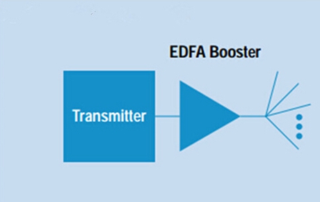
EDFA booster optical amplifier

Placed at the Intermediate Points: as shown in the figure below, the EDFA in-line amplifier can be put at any intermediate point along the long transmission link. This kind of EDFA optical amplifier is designed with low input power, high output power, high optical gain and low noise figure, which are normally deployed every 80-100 km to amplify signals between any two link nodes on the main optical link, with the aim of compensating the loss caused by fiber transmission and other factors. Thereby, the optical signal level can stay above the noise floor.
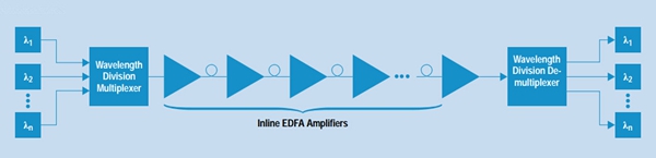
EDFA optical in-line amplifier

Placed at the Receiving Side: EDFA optical amplifier operates at the receiving side of the link is also referred to as pre-amplifier, which has the features of medium to low input power, medium output power and medium gain. This optical pre-amplifier put before the receiver end of the DWDM link is to compensate for losses generated by the demultiplexer located near the optical receiver. With the use of pre-amplifier, the optical signal level can be enhanced before the photo detection, hence improving the receive sensitivity for a long-haul fiber DWDM link.
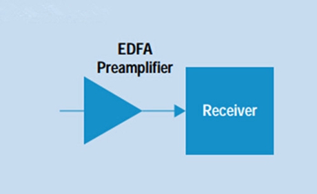
EDFA pre-amplifier

Conclusion
In conclusion, the EDFA optical amplifier can be deployed as booster optical amplifier in the transmitting side of the DWDM link to provide high input signal power for the wide fiber span. It can also work as in-line amplifier at the intermediate point along the link for compensating the fiber loss in the transmission link. What’s more, as the pre-amplifier deployed in the receiving end, it amplifies the signal power to the the necessary receiver level. No matter where the EDFA optical amplifier is deployed in the DWDM link, the signal power can be always enhanced for making a longer DWDM system.

Thursday, May 25, 2017

How to Build an Economical Long-haul 500Gbps Metro Network?

Through years of persistent endeavor, experts have already published 40Gbps and 100Gbps solutions to address the need for higher bandwidth, which have been gradually used for bandwidth-hungry applications. In spite of this, the trend for higher bandwidth seems never ending and now 500Gbps solution for Metro network has been also put forward for thousands of kilometers transmission, in order to meet the increasing network requirements. Considering that the deployment cost for 500Gbps Metro network is very high, the following will offer a cost effective 500Gbps solution that utilizes singlemode fiber patch cable, DWDM Mux and Demux and optical amplifier to build the long-haul 500Gbps Metro network.

Singlemode Fiber Patch Cable for 500Gbps Metro Network
As we know, many fiber patch cables are required in the long point-to-point connections, which would cost high. Hence, in order to build an economical long-haul 500Gbps Metro network, it is necessary to take the fiber patch cable cost into account. Which kind of fiber should be used for the long-haul 500Gbps network? Can it save the cost? Is there any solution to save fibers? The following text will seek the answers.

Singlemode fiber patch cable is undoubtedly the best choice for long-haul 500Gbps Metro network. But its cost would takes a certain percentage in the whole network budget. How to solve it? Under this case, using DWDM technology to deploy the 500Gbps network is highly recommendable that requires only one singlemode fiber to transmit multiple signals, allowing for a big cost saving. When it comes to DWDM network, the DWDM Mux and Demux can’t be ignored. It is the most indispensable optical component to multiplex and demultiplex signals with different wavelengths, which make the 500Gbps transmission over one singlemode fiber possible. In order to save fiber cost, let’s learn how to deploy 500Gbps DWDM network over one singlemode fiber patch cable, instead of point-to-point fiber connections.

DWDM Mux and Demux for 500Gbps Metro Network
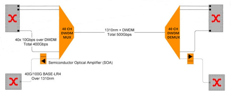
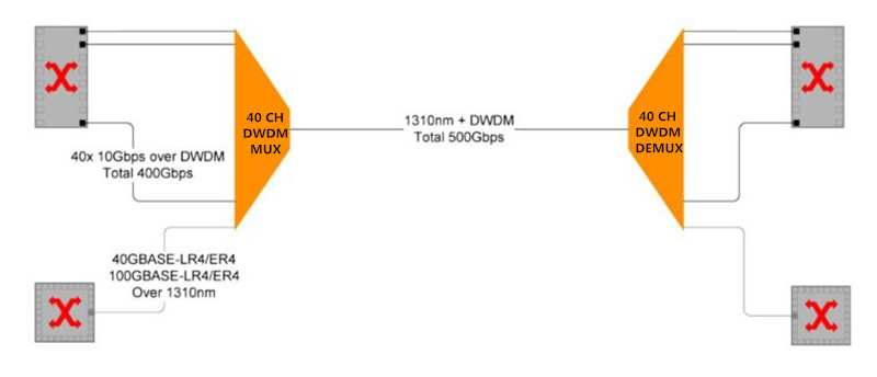
How to use the DWDM Mux and Demux to deploy a cost effective 500Gbps network? Firstly, we should choose two 40 channels DWDM Mux and Demux and insert the 10G DWDM SFP+ transceivers into the 40 channels. Hence, a total 400Gbps load is achieved. Secondly, utilizing the extra 1310nm or 1550nm port on the DWDM Mux and Demux with the 100G QSFP28 LR4/ER4 transceiver to support a total 100Gbps transmission. Hence, the whole transport 500Gbps (400G + 100G) can be finished. If you only need a 440Gbps network, you can just insert the 40G QSFP+ LR4/ER4 transceiver into the extra port. What should be noted is the wavelength of the 100G or 40G transceiver should be the same to that of the extra port. To better know how does the 500Gbps network work, here offers a figure that illustrated the network design to run such huge network load over a single fiber.

http://www.chinacablesbuy.com/wp-content/uploads/2017/05/DWDM-Mux-and-Demux-for-500Gbps-Metro-network

Optical Amplifier for Long 500Gbps Metro Network
Although the singlemode fiber patch cable and DWDM Mux and Demux can address the 500Gbps issue, we still need to use optical amplifiers including semiconductor optical amplifier (SOA) and erbium-doped fiber amplifier (EDFA) to enhance the signal power when the 500Gbps transmission distance is quite long. As shown in the following figure, the semiconductor optical amplifier is deployed in the extra link for boosting the 100G signals, which can extend the transmission up to 60 km. While the erbium-doped fiber amplifier should be deployed in the DWDM transmission link to enhance the 40 10G signals, enabling hundreds of kilometers transmission. Hence, the long 500Gbps Metro network can be finally built.

Optical Amplifier for 500Gbps Metro network

Conclusion
Due to the high cost for upgrading the current network equipment to higher data rate, it would be be more cost effective to build a long-haul 500Gbps DWDM Metro network with the use of DWDM Mux and Demux and optical amplifier (semiconductor optical amplifier and erbium-doped fiber amplifier). The DWDM Mux and Demux makes the 500Gbps network load possible through a single fiber, while the optical amplifier allows the 500Gbps signals to be transmitted longer. These two DWDM optical components are very critical to deploy the economical long-haul 500Gbps Metro network.

Thursday, May 11, 2017

Analysis of A Practical CWDM System Deployment Case

As the need for high capacity increases so fast, the WDM (wave division multiplexing) technology meets with great favor in today’s optical network that can be mainly divided into CWDM (coarse wave division multiplexing) and DWDM (dense wave division multiplexing) technology. Although the CWDM cannot transmit the signals so long as that of DWDM, it costs much less to deploy the WDM system and keeps the scalability to increase the network capacity. For this reason, CWDM technology is much more popular then the DWDM one. In this post, it will simply study the two key components for deploying a CWDM system and analyze one practical CWDM system deploying case for you.

Key Components for Deploying CWDM System
CWDM technology is to multiplex multiple wavelengths for transmitting several kinds of signals through only one fiber, with the aim of solving the capacity-hungry issue. As the CWDM system is more complicated than a common system which consists of much more components, it is necessary to know the key components used for building CWDM system before learning the practical CWDM system deployment case.

CWDM Mux Demux: it is the basic and key component for a CWDM system. It is designed for multiplexing 4, 8 or even 16 different wavelengths to transmit up to 16 kinds of signals as an integrated signal over one fiber at the same time and then demultiplexing the integrated into individual signals. That’s to say, 3, 7 or even 15 virtual fibers are created in the process with much higher capacity. If you are facing the capacity-hungry issue, then the compatible CWDM Mux Demux would be a necessity for you to deploy a higher capacity system.

CWDM OADM: it can be also called CWDM Optical Add Drop Mux. It is mainly used for add and drop (multiplex and demultiplex) channels on both directions in a CWDM system. You can use the Add Drop Mux to add new access points in anywhere of your CWDM system, which has no influence on the other channels.

Practical CWDM System Deployment Case
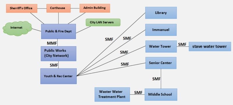
In this case, singlemode fiber cable or multimode fiber cable are used for connecting five buildings including Sheriff, Courthouse, Admin, Police & Fire Dept, and Public Works, as shown in the following figure. It deploys a simple network in city offices. But now, we should use the singlemode fiber cable to deploy a complete system that should link numerous buildings in the town. In details, the Public Works should connect with Youth & Recreation Center, Library, Immanuel Lutheran School and the Senior Center, both of which have unfiltered Internet. Meanwhile, the Waster Water Treatment Plant is designed to link with Middle School and then connect the Senior Center.

Case Detail

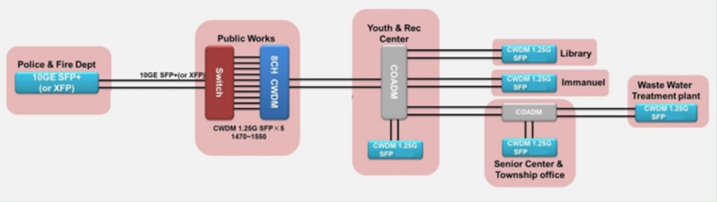
What can we do to meet the requirements? The answer is building a CWDM system. The following figure shows the detailed solution. 8 channel CWDM Mux Demux is used to connect the switch. Since the four buildings Youth & Rec Center, Library, Immanuel and Senior Center should be connected with the Public Works that need unfiltered services, we should put a 4 channel CWDM OADM behind the 8 channel CWDM Mux Demux. Hence, four signals with different wavelengths can be drop and transmitted into these four buildings. On the other hand, to meet the another requirement, we should put a CWDM OADM on Senior Center to serve the Waster Water Treatment Plant.

CWDM Solution for the Case

Conclusion
After learning the practical CWDM system deployment case, do you also want to deploy a CWDM system like this for higher capacity? If yes, the key components like Mux Demux and OADM for building CWDM system are available at FS.COM with good price. Except these two devices, other components for WDM system like EDFA amplifier, dispersion compensation module and WDM Transponder are also available.

Friday, May 5, 2017

Why Do We Need Optical Transponder (O-E-O)?

Nowadays, more and more data centers utilize the WDM technology to gain bigger capacity for various applications, such as, 10G LAN, SONET/SDH, Fiber Channel, etc. Through this method, we can not only reduce the multiple fiber use, carry the signals through only one fiber, but also expand our network capacity. Since there are such benefits from WDM technology, why not use it to deploy our network? At present, there are various kinds of equipment required for WDM system, for instance, WDM Mux Demux, optical fiber amplifier and optical transponder. To build a high performance WDM network, this paper will mainly introduce the optical transponder, an important component in the WDM network, and illustrate why we need optical transponder.

What’s Optical Transponder (O-E-O)?
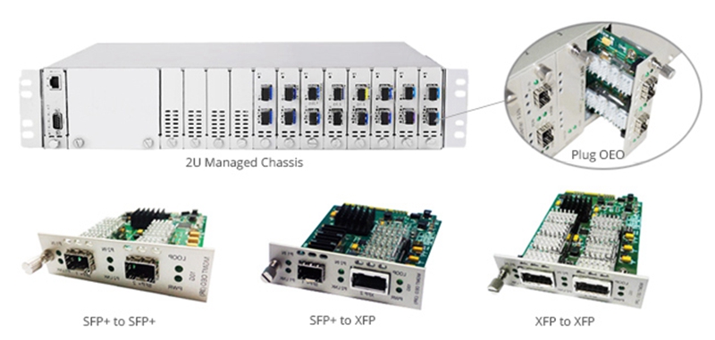
Optical transponder is an optical component designed for amplifying and shaping signals, and even for converting the wavelength and the pattern of the signals, which is commonly used in optical transmission. It can be also reffered to as WDM converter, OEO converter or WDM transponder. With the use of optical transponder, the optical transmission distance can be much extended and the cost for deploying long transmission can be highly reduced. It is really an cost effective solution for long transmission. Furthermore, it features small and handy shape which is very easy to install. To better know the optical transponder, here offers a kind of 10g transponder that enables SFP+ to XFP, SFP+ to SFP+ or XFP to XFP fiber connections.

10G Transponder

Why Do We Need Optical Transponder (O-E-O)?
The optical transponder can be applied in various occasions for different aims. For instance, it can be regarded as optical repeater, signal wavelength converter, transmission mode converter, etc, for optimizing the signal quality, extending the transmission distance, converting the signal wavelength and the transmission mode. Let’s study these common functions of the optical transponder.

Optical Repeater: the optical transponder can act as an optical repeater to amplify the signals, so that transmission distance can be extended. Meanwhile, it can also dejitters and retransmits the degraded signal for optimizing the signal quality. Hence, a smoother, longer transmission can be achieved.

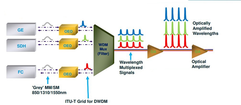
Signal Wavelength Converter: the optical transponder is always used as signal wavelength converter. It can convert an original kind of signals into several kinds with different wavelengths, hence the WDM network connection can be built on the base of a traditional network connection. When the signals pass through the optical transponder, they can be received, converted and transmitted with other kinds of wavelengths. But the signal content will not be changed in the process. To illustrate how the optical transponder works as signal wavelength converter, the following figure shows the signal wavelength conversion from traditional 850 nm, 1310 nm and 1550 nm into DWDM wavelengths in 10G LAN, SONET/SDH, Fiber Channel applications for your reference.

OEO for Signal Wavelength Convertion

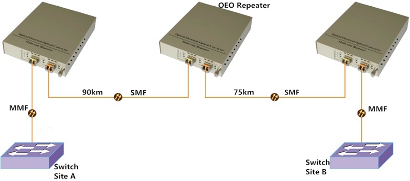
Transmission Mode Converter: we can also use the optical transponder to change the fiber transmission mode, such as, converting multimode into singlemode transmission and duplex into simplex transmission. Here offers a multimode into singlemode convertion design as an example. From the figure, you can learn that the signal is firstly transmitted through multimode fiber. And after passing through the first optical transponder, it can be transmitted through singlemode fiber at lengths 90 km. To extend the transmission distance, the second optical transponder is deployed and the transmission is extended from 90 km to 165 km. Finally, the signal will pass through the third optical transponder and the transmission mode will be converted into multimode again. Thereby a long singlemode transmission up to 165 km can fit with the existing multimode system.

OEO for Fiber Mode Convertion

Conclusion
It can’t be denied that the optical transponder plays an important role in our network. It can not only highly extend the transmission distance, but also increase the network capacity by converting the traditional signals into CWDM or DWDM signals to fit with the WDM system. What’s more, it can also change the fiber transmission mode. Except for these common functions, there are still several functions not mentioned, for instance, offering a redundant fiber path for extra protection. Then, why not use the optical transponder to optimize our network?

Thursday, April 20, 2017

Confused About Loss in the Long Haul DWDM Network?

As the optical network develops fast, today’s network needs much higher capacity than ever before, for carrying the large amount of data. Under this trend, the DWDM technology is come up with that can greatly expand the network capacity in long haul transmission. For those capacity-hungry applications, building a DWDM network is undoubtedly an economical solution that can transmit much more signals through only one singlemode fiber for a long distance. However, the DWDM network is very complicated which consists of various components like DWDM Mux Demux, EDFA optical amplifier and dispersion compensating module. Taking all these components into consideration, the detailed loss in the long haul DWDM network would be a puzzle for many users. To clear up the confusion, this paper will analysis what mainly cause the loss in the long haul DWDM network and learn how to calculate the loss budget in details.

What Mainly Cause the Loss in Long Haul DWDM Network?
 
It is well known that any components inserted into the a network will cause loss, more or less. For instance, if a DWDM Mux Demux for multiplexing signals is deployed in the network, the insertion loss will occur. Hence, when designing a DWDM network, you are highly suggested to make the whole loss budget clear, for ensuring the performance of your network.

DWDM Mux Demux: a key component in the DWDM network. It is designed for multiplexing several kinds of signals with different wavelengths and then carrying the integrated signal through one fiber. Considering that Mux Demux is a passive component without the function of amplifying the signals, its big insertion loss will affect the whole network loss. In order to reduce the cost for deploying the DWDM network, it is very necessary to choose a DWDM Mux Demux with less insertion loss.

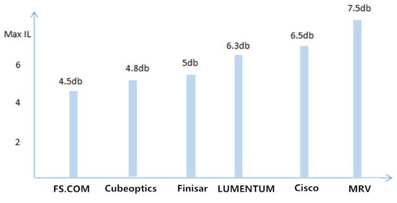
 40 Channel DWDM Mux Demux Insertion Loss comparison

In recent year, most DWDM Mux Demux manufacturers dedicate the reduction of insertion loss. Since the insertion loss are still very different among these manufacturers, here offers a figure that shows their maximum insertion loss of the 40 Channel DWDM Mux Demux. From the figure, we can learn six common DWDM Mux Demux manufacturers who provide the 40 Channel DWDM Mux Demux. Among these manufacturers, FS.COM, Cubeoptics and Finisar offers the Mux Demux with relatively low insertion loss that are high recommended, while others don’t.

Optical Add Drop Mux: another component deployed in the DWDM network. From its name, it is easy to learn that it enables individual or multiple wavelength channels to be added or dropped from an incoming link. When it is working, the signal will pass from the common port to add/drop port or from the add/drop port to the common port. The insertion loss will be caused during the process.

Dispersion Compensation Module: plays an important role in DWDM network. When the optical signals are deformed by the chromatic dispersion in the transmission, we can use this component to reshape the deformed signals. As it is very useful for receiving the right signals and avoiding transmitting errors, it is required to be inserted in the receiver end of the DWDM network which also cause the insertion loss.

Other Components: apart from the mentioned components, the singlemode fibers can also cause loss in DWDM network. Moreover, the longer the transmission distance is, the higher the loss will be. In addition, the EDFA optical amplifier should be also noted. When the loss in the DWDM network is too high and can’t support the long transmission, the EDFA optical amplifier will be used for boosting or adding gain of optical signals. Hence, the signal power can be balanced and the long transmission can be done.

How to Calculate the Loss Budget for the DWDM Network?
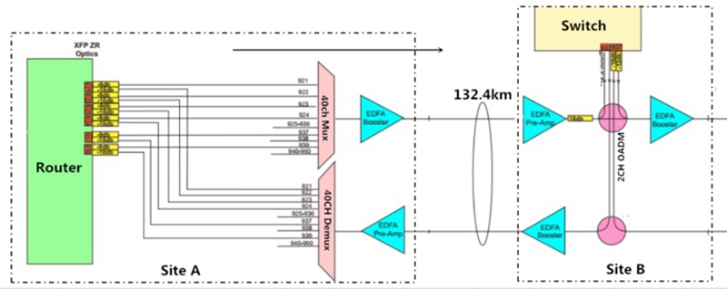
To understand how to calculate the whole loss budget, here offers a part of the long haul DWDM network deployment solution, designed by a user from UK. From the figure, we can learn the whole transmission distance is 132.4 km, from site A to Site B. The 40 channel DWDM Mux Demux, booster EDFA optical amplifier, pre-amplifier, 2 channel optical add drop mux and optical attenuators are installed for deploying the DWDM network. All these components will cause the loss or change and affect the whole network performance.

Long Haul DWDM Network Design

Now let’s calculate the budget loss from site A to site B:

A. The first loss of the link is caused by the use of an optical attenuator, between the router and the 40 channel DWDM Mux. It is -8.5dB.

B. When the signals pass through the DWDM Mux, the second loss, -4.5dB occurs. Then the output power is:-8.5dB-4.5dB =-13dB.

C. Then the signal will be boosted by the EDFA optical amplifier, and there is +23dB gain. At this time, the signal output power is: -13dB+23dB= +10dB.

D. Considering that the total loss of the fiber optic cable is: -0.22dB/km x132.4km = -29.13dB, the input power of the pre-amp EDFA is: +10dB-29.13dB = -19.13dB.

E. As the pre-amp EDFA gain is +26dB, so the output power is +6.87dB.

F. There is an attenuator with -18dB loss installed after the pre-amp EDFA. Hence, the output power after the attenuator is: +6.87dB-18dB = -11.13dB.

G. To enhance the signal, another EDFA optical amplifier installed in the receiver end. So that, the output power of site B is: +23dB-11.13dB=+10.67dB.

Conclusion
 
Since there are various components like EDFA optical amplifier, dispersion compensation module, optical add drop Mux and patch cables needed for building a long haul DWDM network, the loss may occur many times during the transmission. Hence, calculating the loss budget before building the DWDM network is very necessary. Only by making the whole loss budget clear, the power loss in the transmission can be controlled and the whole DWDM network performance can be ensured.

Thursday, April 13, 2017

CWDM Technology—Economically Saving Fibers for Your Network

What’s CWDM Technology?
 
CWDM, also referred to as coarse wavelength division multiplexing, is a kind of WDM technology that uses different wavelengths to multiplex two or more optical signals and carry them together via a single optical fiber, aiming at enhancing the network performance. Instead of putting more fibers to carry larger data volume, CWDM technology enables many virtual fibers to meet the increasing requirement of network capacity, as an economical cabling solution for fiber infrastructures. In principle, it can carry up to 18 wavelengths on a single fiber in the spectrum grid from 1270 nm to 1610 nm with a 20nm channel spacing, which can support the network at lengths up to 80 km.

In contrast with the DWDM channel spacing, the CWDM channel spacing is too large that makes its channel design not so complicated as the DWDM one. As a result, the optical signals in CWDM channels are not able to be amplified by the optical amplifiers as those in the DWDM channels. Accordingly, CWDM technology can not support the network as long as that of DWDM one. But on the other hand, the feature of wider channel spacing allows more moderate CWDM multi-channel Mux/Demux price and other CWDM equipment prices. In short, CWDM technology is an economical solution to deploy high capacity network with less fibers that reaches up to 80 km.

CWDM Mux Demux—a Key Component in CWDM Network
 
When we talk about the key components in the CWDM system, the CWDM Mux Demux usually comes to our mind firstly that plays a critical role in the CWDM system. The CWDM Mux Demux modules are bidirectional optical multiplexers utilizing different wavelengths to combine multiple optical signals together and transmit them via a single fiber, which always work in pairs to support bidirectional transmission. In details, it can combine up to 18 signals with different wavelengths from 18 separate optical fibers, then transmit them together through a single optical fiber, and finally separate the integrated signal into individual signals again and send them to other 18 separate optical fibers. By this method, it can efficiently expand the network without the need of adding more fibers, which is really a high bandwidth but low cost solution for users.

CWDM Mux Demux for Dual Fiber CWDM Network
 
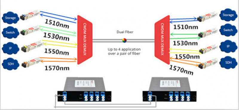
The CWDM Mux Demux used for building dual fiber CWDM network can be also called dual fiber CWDM Mux Demux, which is an universal device with the advantages of good performance and environmental stability. There are up to 18 CWDM wavelengths between 1270 nm to 1610 nm with 20nm channel spacing that can be used for the dual fiber CWDM Mux Demux. Just taking a 4 channel dual fiber CWDM network as an example, there are four kinds of wavelengths separately used for the two 4 channel CWDM Mux Demux and the ports on these two Mux Demux have the same TX and RX, as shown in the following figure. The signals with four different wavelengths transmitted from left to right should be multiplexed in the left Mux Demux, transmitted via the first single fiber and demultiplexed in the right Mux Demux, and vice versa for the transmission from right to left.

4 Channel Dual Fiber CWDM

CWDM Mux Demux for Single Fiber CWDM Network

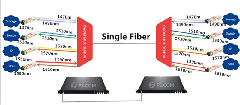
As for the single fiber CWDM Mux Demux, it is more complicated than the previous one that can be learned from the following figure. By comparison, there should be eight wavelengths used for a 4 channel single fiber CWDM network, which is the twice as much as that of a 4 channel dual fiber CWDM network. The eight wavelengths will be divided into four pairs separately used for the four channels and the TX and RX of the ports on the two single fiber CWDM Mux Demux are all reversed to finish the dual way transmission. For instance, the first port on the left Mux has 1470 nm for TX and 1490 nm for RX, while the first port on the right one has 1490 nm for TX and 1470 nm for RX. Hence, the first signal with 1470 nm can be transmitted via the single fiber from the left to the right, while the signal with 1490 nm can be also oppositely transmitted via the same fiber.

4 Channel Single Fiber CWDM Network

Conclusion
 
CWDM solution is a cost effective choice for increasing the network capacity and promoting the network performance. By this method, you can use less fibers for sending the same amount signals. If you are facing the capacity-hungry issue, you are recommendable to use the compatible CWDM Mux Demux, CWDM transceivers, duplex or simplex singlemode patch cables and related CWDM equipment to build a high-capacity CWDM network.